
FX1000 · Building Plans
Steering System Plan for Crosskart Buggy
This is the technical drawing to build the steering system for your crosskart buggy.
- 28 pages
- English
- iDEAL, cards, PayPal and Apple Pay
What's inside the plan
From novice builders to seasoned enthusiasts: clear instructions and production drawings that take you from tubes and plates to a finished buggy.
Build sequence
Step-by-step order of work for every module, so you always know what comes next.
Production drawings
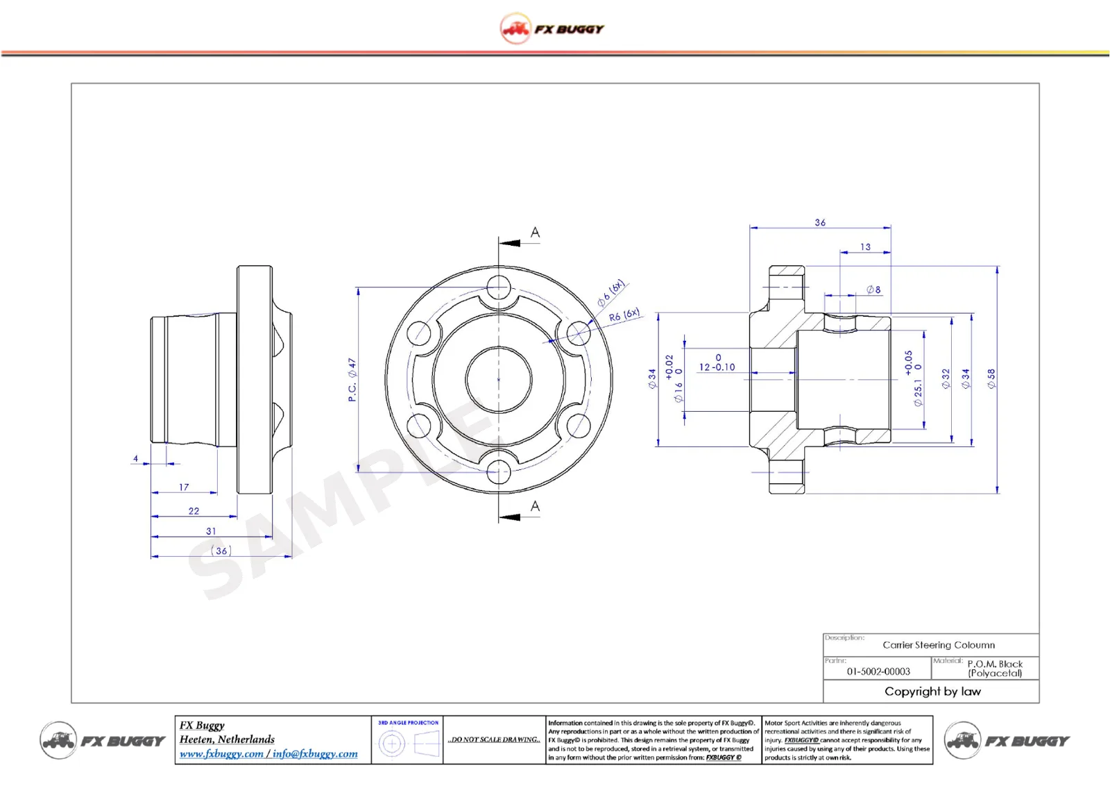
Dimensioned drawings for every custom part: tubes, plates and machined parts, with tolerances for the precision parts.
1:1 welding jigs
Printable full-size drawings to use as welding jigs, for example for the A-arms.
Assembly instructions
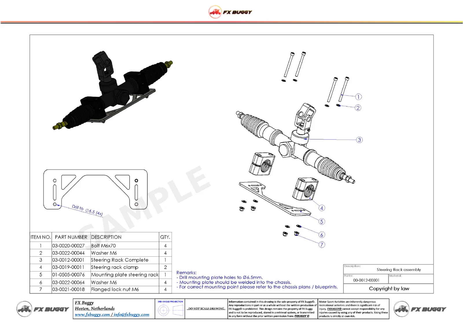
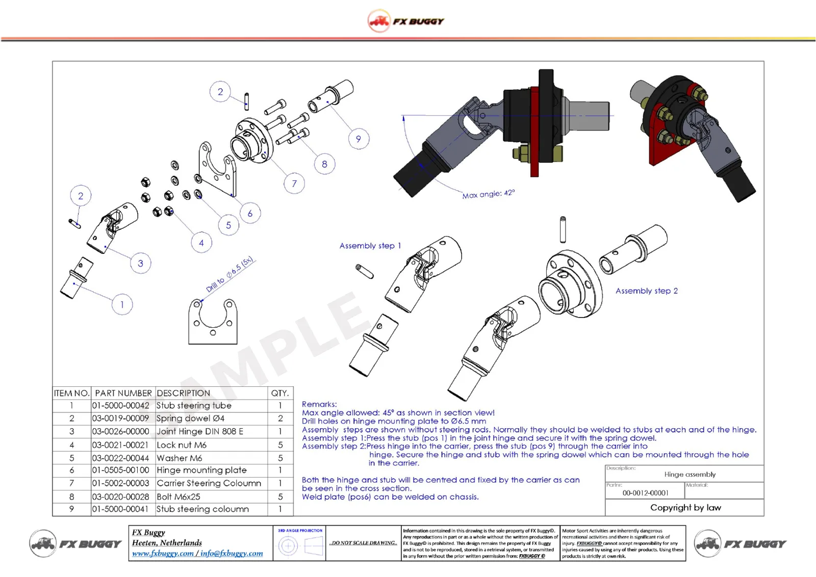
Exploded views with numbered parts, so every assembly step is clear. The engineering is already done.
Parts lists
A bill of materials per module. Part numbers match the part numbers in our shop.
Safety checklist
What to check before every ride: steering, brakes, welds, bolts, chain, tyres and throttle cable.
Sample pages
About this product
This plan contains 28 pages with highly detailed assembly and production drawings, part lists and descriptions.
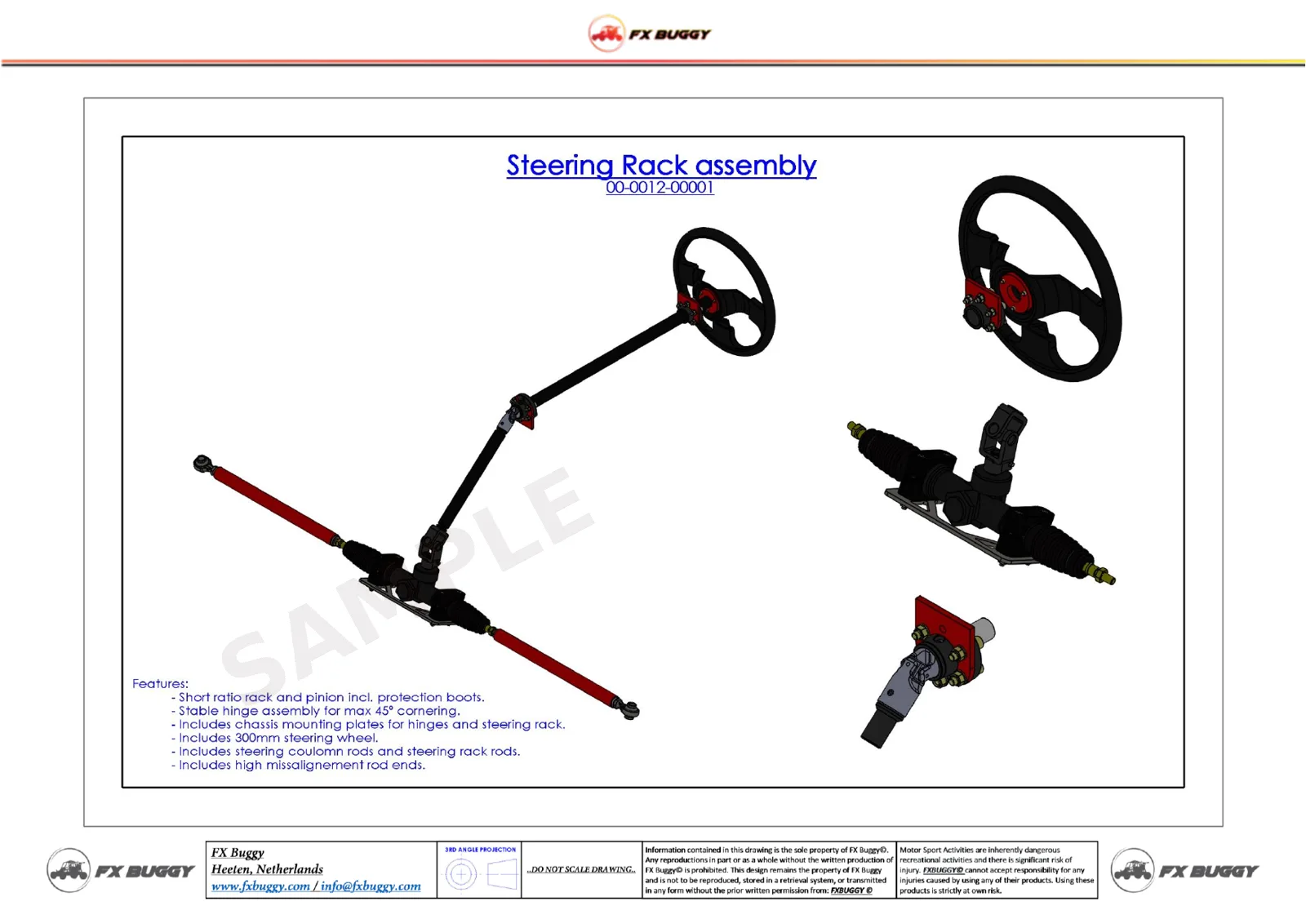
The steering system has a short ratio rack and pinion including protection boots and a 300 mm steering wheel for quick change of direction. A stable HD joint hinge is constructed for tipping points in the steering column. The hinge, steering rack and steering wheel assembly’s includes mounting brackets and fasteners in the plans. The steering column is made out of seamless Ø24 x 3.0 mm tubes. Steering rods of Ø22 x 2.0 mm tubes. High alignment rod ends on upright side.
This plan is a downloadable file. You will receive a PDF file, which can be downloaded immediately after purchase.
- Short ratio rack and pinion incl. protection boots
- Stable hinge assembly for max 45º cornering
- Chassis mounting plates for hinges and steering rack
- 300 mm steering wheel
- Steering column rods and steering rack rods
- High misalignment rod ends
Technical specifications
| Part number | 02-0000-00007 |
|---|
Part of the FX1000 build
Where this fits
- Module 1 Frame
- Module 2 Front suspension
- Module 3 Rear suspension
- Module 4 Center hub
- Module 5 Pedal box
- Module 6 Steering You are here
- Module 7 Gear lever
Questions builders ask
How do I receive the plan?
Right after payment you get a download link by email and in your account.
Which engines fit the FX1000?
Chain-driven motorcycle engines with an internal sequential gearbox, up to 180 hp and 120 Nm. For a first build we advise a 600 cc fuel-injected engine.
Do I also need the laser files?
The plan has drawings of every part. With the laser files (DXF) a laser cutting shop can cut all sheet metal parts straight away, so you don't have to draw them yourself.
What skills and tools do I need?
You need to read technical drawings and weld (MIG/MAG for the frame and A-arms, TIG for small parts), and cut and bend tubes or buy them bent. A small press and a heat source for the bearings; further standard tools.
Ask the engineer
Not sure this fits your build, or stuck on a detail? Ask the people who designed it.
Within the EU you pay 21% Dutch VAT; outside the EU no VAT is charged. Checkout calculates it from your shipping address. Read more about VAT
Physical products: 14 days to change your mind. Plans and laser files can't be returned. Terms and conditions
All fields are required.
